
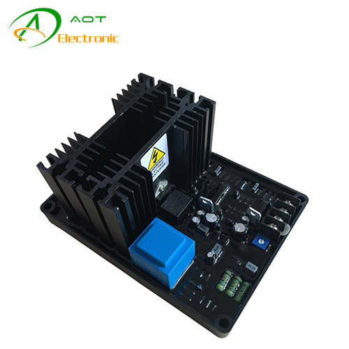
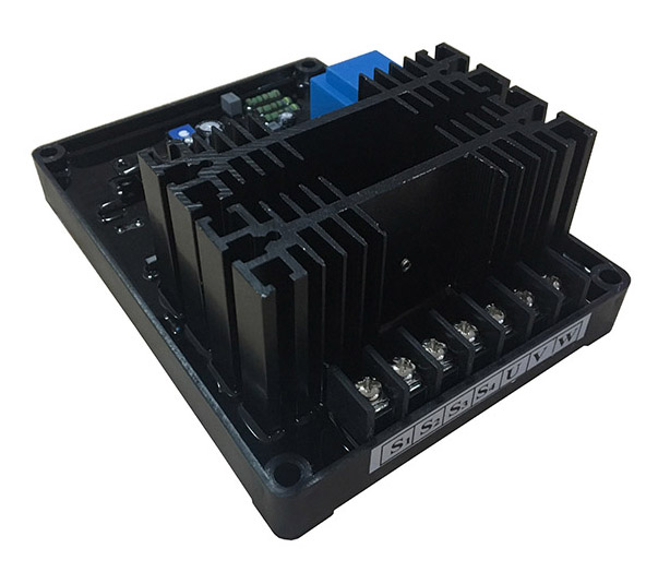
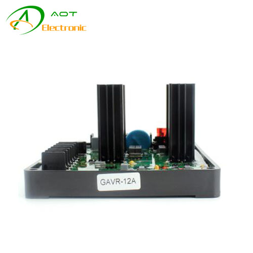
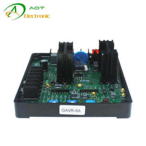
Brush Generator AVR Circuit Diagram GB-130 is a single phase controlled Thyristor type Automatic Voltage Regulator and forms part of the excitation system for a brush generator. In addition to regulating the generator voltage, the AVR circuitry includes under speed and sensing loss protection to ensure safe, reliable control of the generator.
Positive voltage build up from residual levels is ensured by the use of proficient semiconductors in the power circuitry of the AVR. Which is linked with the main stator windings and the exciter field windings to offer closed loop control of the output voltage with load regulations of +/- 1.5%
|
Model |
Brush Generator AVR GB-130 |
|
|
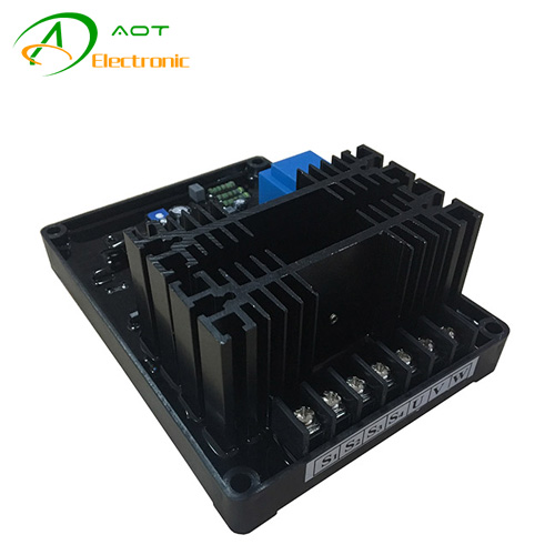
Sensing/Power input |
Voltage |
400V AC, 1 phase 2 wire |
|
Frequency |
50-60 Hz nominal |
|
|
Phase |
1 |
|
|
Voltage |
20-100VDC |
|
|
Magnetic Field Output |
Current |
20A |
|
Resistance |
15 ohms minimun |
|
|
Pressure Regulating Accuracy |
|
<±1% RMS with 4% engine governing |
Contact: Jack
Phone: 0086-19906045242
Tel: 0086-592-7161550
Email: sales@aotchina.com
Add: No.21 Yufu Road, Jimei Disctrict, Xiamen City, China 361000
 QQ: 865131846
 Skype: sales@aotchina.com