
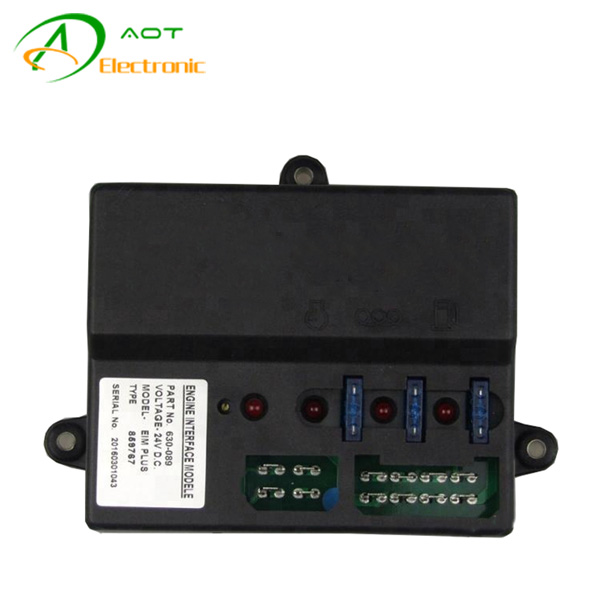
Generator Parts Engine Interface Module Controller EIM PLUS 630-089
12V Olympian FG Wilson PCB :
650-091 PCB, 12V for Olympian or F.G. Wilson 12 volt engine control. Replaces PC Board 650-091.
24V Olympian FG Wilson PCB :
650-092 PCB, 24V for Olympian or F.G. Wilson 24 volt engine control. Replaces PC Board 650-092.
|
Generator Parts Engine Interface Control Module for FG Wilson |
|
|
EIM PLUS |
|
|
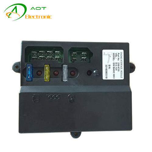
258-9753 12V |
258-9754 12V |
|
258-9755 24V |
258-9756 24V |
|
|
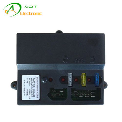
630-465 12V |
|
|
630-466 24V |
|
|
630-088 12V |
|
|
630-089 24V |
|
|
917-423 12V |
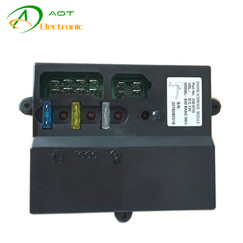
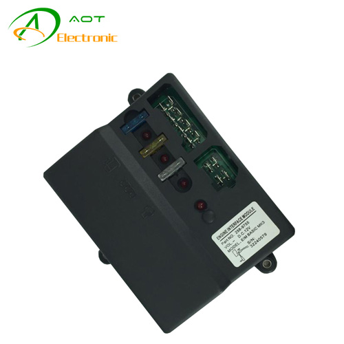
Specifications of Engine Interface Module 630-089
The FG Wilson Engine Interface Module is a sealed engine mounted module that provideds switching Relays for the starter motor Solenoid, glow plug and fuel solenoid.
Each of these circuits is protected with individual automative fuses mounted in the module. Individual LED’s illuminate when each circuit is energized in addition these LED’s greatly aid when fualt finding.
This module is mounted on the engine with anti-vibration mounts and is easily connected to the engine via loom plugs. Use of the FG WILSON EIM 630-089 means that heavy currents such as fuel solenoid power are isolated from the control panel thus enabling individual protection of each of the circuits.
How to Install FG Wilson EIM?
1. Ensure the MPU(Magnetic Pickup) is installed correctly.
2. Unscrew and pull out the magnetic pickup that is located near the flywheel of the engine
3. Inspect the magnetic tip and ensure that is it clean and free of debris.
4. Screw the MPU in until the tip makes contact with the top of the flywheel teeth.
5. Back out the magnetic pickup 1/2 to 3/4 of a turn.
6. Turn the ten-turn potentiometer between five to seven turns clockwise or just until you feel a small click-signifying the full span of the pot.
7. Start the generator set,you will notice the overspeed calibration LED illuminated.
8. Slowly turn the potentiometer counter-clockwise until the LED just turns off.
9. As soon as the LED turns off,start to slowly turn back the potentiometer clockwise just until the led starts to flicker.


Contact: Jack
Phone: 0086-19906045242
Tel: 0086-592-7161550
Email: sales@aotchina.com
Add: No.21 Yufu Road, Jimei Disctrict, Xiamen City, China 361000
 QQ: 865131846
 Skype: sales@aotchina.com